
TOKYO RIKAKIKAI CO., LTD.
HOME > Frequently Asked Questions (FAQ)
Use this information to help resolve questions regarding the selection, operation, and maintenance of EYELA products.
Product selection of rotary evaporators and concentrators
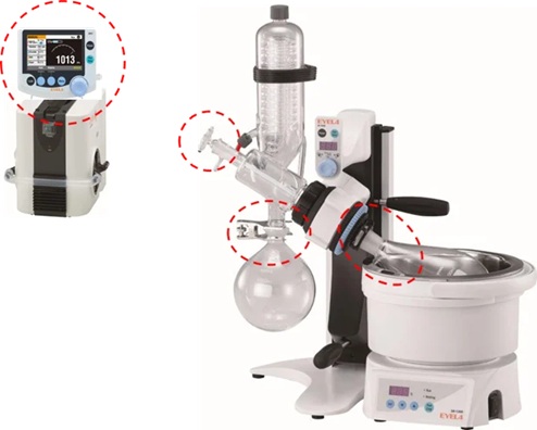
We provide a video showing installation examples for the N-1300E rotary evaporator, including how to install the rotary joint and key precautions, as well as important points to consider when attaching the vacuum seal.
It is a device designed to collect organic solvents under atmospheric pressure.
The model DPE captures solvents using a condenser installed on the exhaust side of a vacuum system. Since there is no boiling-point reduction caused by vacuum, it allows the recovery of organic solvents that cannot be collected with a rotary evaporator under reduced pressure (excluding certain low-boiling solvents).
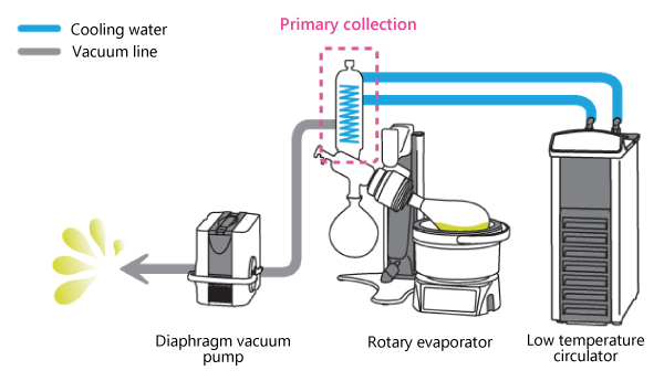
Under reduced pressure, solvents are collected by the condenser of the rotary evaporator. If the temperature difference between the sample and the condenser becomes small due to the vacuum level, certain organic solvents may not condense sufficiently and can be discharged through the vacuum pump.
Collection under atmospheric pressure with the model DPE. Except for certain low-boiling solvents, the large temperature difference between the sample’s boiling point and the condenser temperature under atmospheric conditions enables efficient collection of organic solvents that cannot be recovered using a rotary evaporator.
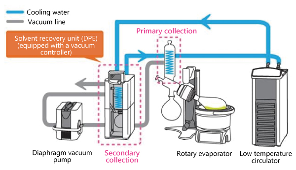
When using the solvent recovery unit (model DPE) for concentration systems, the cooling water should be supplied from the DPE unit.
If the cooling water is supplied from the rotary evaporator condenser, the heat exchange during distillation warms the cooling water before it reaches the DPE unit, reducing its collection efficiency. In contrast, when the cooling water flows from the DPE unit, almost no heat exchange occurs on the DPE side, ensuring that the condenser of the rotary evaporator maintains its optimal cooling performance.
Depending on the sample volume, we recommend installing a cold trap.
When a sample transitions from liquid to vapor, its volume increases significantly, making it difficult for a vacuum pump alone to handle the load.
Using a cold trap condenses the vapor back into liquid or solid form, allowing the vacuum pump to discharge only non-condensable gases. This makes it easier to maintain the required vacuum level and improves the efficiency of the evaporation process.
The adsorption cartridge is a consumable component, and its typical replacement interval is approximately three months.
However, the actual service life varies depending on the type of samples, operating conditions, and the amount of solvent being adsorbed.
The main differences lie in the concentration method and the required processing time.
The TVE test tube evaporator and the CVE centrifugal evaporator perform concentration under reduced pressure, while the MGS pressure gas blowing concentrator operates at atmospheric pressure.
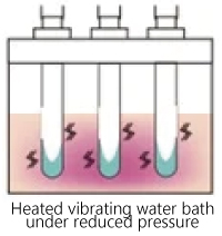
Under reduced pressure, the sample vessel is directly heated in a water bath, providing highly efficient evaporation.
Among these systems, it offers the fastest concentration performance.

The sample containers are heated by radiant heat under reduced pressure.
Because multiple tubes can be processed at the same time, handling is straightforward and efficient.
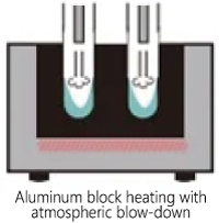
Moisture in the samples is evaporated by blowing air or inert gas directly onto them at atmospheric pressure.
This compact system can process many tubes simultaneously, and with no mechanical moving parts, it offers high reliability and minimal risk of mechanical failure.
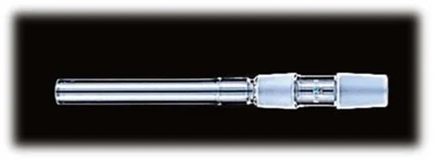
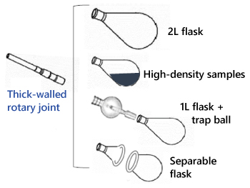
In addition to the standard type, rotary evaporators can also be equipped with a thick-walled rotary joint.
What is the specific purpose of a thick-walled rotary joint, and how does it differ from the standard one?
Troubleshooting for the rotary evaporators
The following are general precautions when performing concentration with a rotary evaporator:
Startup and preparation
Contamination (sample contamination)
1. Contamination caused by bumping
2. Contamination from the Evaporator
Denaturation
Please check the following items:
If the rotary evaporator does not reach the set pressure on the vacuum controller, please check the following:
Note: If the vacuum pump is faulty, liquid may have entered the hose or the pump. Run the pump empty to discharge any liquid. If the problem persists, the diaphragm may be worn or deteriorated.
Note: If the evaporator has a vacuum leak, check the following items and replace any worn or deteriorated parts.
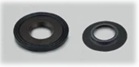
Are the vacuum seals worn or deteriorated?

Is the rotary joint worn? (The area where it contacts the vacuum seal can sometimes wear down.)

Is the packing on the nozzle worn, degraded, or deformed?
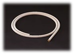
Is the vacuum hose cracked, hardened, or otherwise deteriorated?
Note: Please refer to the instruction manual for the Cat. No. of consumables and the replacement procedures.
If only a small amount of liquid is dripping into the receiving flask compared to the amount in the sample flask, please check the following:
Note: Excessive vacuum can cause the solvent to be drawn into the pump or to re-evaporate from the receiving flask, reducing recovery. Please use an appropriate cooling water temperature (15 to 20°C below the solvent’s boiling point) and a vacuum level suitable for the solvent.
If the bath temperature does not rise, with the power switch ON, please check the following:
Note: Please contact your distributor or our service center for assistance.
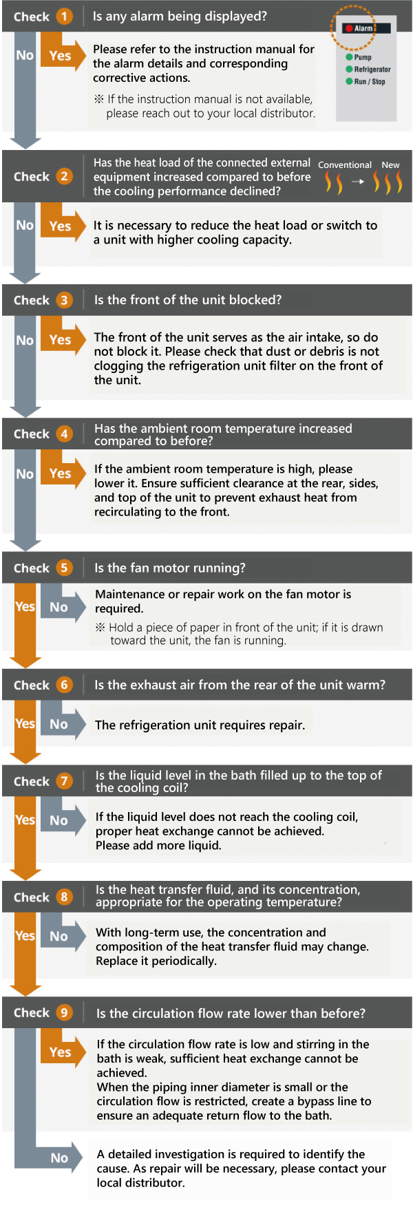
Please check items 1 through 9 below to help identify the cause. If the cause cannot be determined, the unit will require repair. Please contact your local distributor or EYELA.
Find your local distributor.
A chiller cools the target sample or equipment (or a part of the equipment) by removing heat.
The heat removed must then be discharged by the chiller itself.
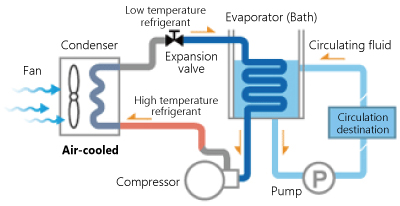
Chillers are available with two types of heat dissipation systems—air-cooled and water-cooled—allowing users to select the most suitable option for their application.
Air-Cooled Refrigeration Unit
Water-Cooled Refrigeration Unit
The chiller is equipped with a built-in fan motor, making installation simple. Because heat is discharged into the surrounding air, heat can accumulate in confined spaces and affect cooling performance and service life. In such environments, additional exhaust or ventilation equipment may be required.
Cooling water for the refrigeration unit is required.
This type offers excellent cooling efficiency and does not release exhaust heat into the room, resulting in more stable cooling performance.
Key Points for Chiller Selection
EYELA offers two cooling methods—air-cooled and water-cooled—across its lineup of water chillers (low temperature circulators) and heating circulators. Depending on your application, a wide range of models is available, covering low-temperature, low- to high-temperature, and high-temperature applications. Please select the most suitable model by considering six basic factors, including temperature range and accuracy, as well as cooling capacity.
| Point 1 | Circulation Temperature and Accuracy | What is the required circulation (set) temperature? What temperature control accuracy (±°C) is required? |
| Point 2 | Cooling Capacity | What is the heat load or required cooling capacity? (W) |
| Point 3 | Circulation System | Is a closed-loop or open-loop circulation system required? What is the external circulation target? |
| Point 4 | Circulation Performance | What flow rate (L/min) is required? What discharge pressure or lifting height (m) is required? (MPa) |
| Point 5 | Type of Circulating Fluid | What type of circulating fluid will be used? |
| Point 6 | Environmental Considerations | Does the refrigeration unit use an environmentally friendly, non-CFC or low-GWP refrigerant? |
In addition, factors such as air-cooled or water-cooled type, installation space, piping, and power supply should also be considered.
Pure water is generally defined as water with an electrical conductivity in the range of 0.1 to 0.01 mS/m.
When pure water produced using ion-exchange resin (ion-exchanged water) is used, it may corrode certain components or sealing materials in the unit. As a result, the number of compatible models is limited.
Models CA-1115F / F2 and CA-2600F / F2 can be used without issue even with ion-exchanged water as described above.
If the water has been pretreated without the use of ion-exchange resin—such as purified water, soft water, or distilled water—models such as the CA-1115B, NCC-3000C / 3000D with heater, and NCC-3100C / 3100D can also be used.
The cleaning procedure is demonstrated in a video.
The key criteria are heating capacity and circulation performance.
Please confirm whether the heater wattage of the HS series can achieve the required heating temperature and heating time at the external load, and whether the built-in circulation pump provides sufficient flow rate and discharge pressure.
Factors required for selection
Calculations for heating capacity and circulation performance should be discussed with your local distributor or EYELA Customer Center.
Caution
Check the vacuum level of the unit.
During the drying process, moisture in the sample sublimates, causing the internal pressure (vacuum level) to increase. Once drying is complete and there is no more moisture to sublimate, the internal pressure decreases and returns to the no-load vacuum level. To sublimate bound water in the sample and obtain a drier product, continue operation for several additional hours in this state before stopping the process.
Model selection is based on the amount of sample and the shape of the vessels used. Please select a model by considering the maximum amount of moisture to be processed in a single batch.
Depending on the vessel shape, additional options such as a manifold or shelves (drying chamber) may be required.
For compact models, other options such as a pre-freezing unit and a vacuum pump may also be necessary. Please refer to the combination guide in the catalog and select the required options accordingly.
The compact freeze dryers FDS-2100 and FDS-2200 feature a non-fluorocarbon design that uses a helium gas cooling system. All other models are charged with fluorocarbon refrigerants.
A simple inspection at least once every three months is required in Japan. In addition, when disposing of the product, recovery and destruction of the fluorocarbon refrigerant are required. For further details, please consult the appropriate regulatory authorities in your country.
The oil in the oil rotary vacuum pump used in freeze dryers deteriorates with use. Changes in concentration, viscosity, and vapor pressure due to moisture or solvent contamination, as well as thermal degradation caused by heat generation, can reduce internal sealing performance and affect the ultimate pressure. In addition, the formation of rust or sludge may lead to mechanical failures.
Regular oil replacement is therefore required, using indicators such as changes in oil color or deterioration of the vacuum level.
When pre-freezing samples in freeze-drying bottles or flasks, it is important to freeze the sample as a thin layer along the inner wall of the container in order to improve drying efficiency and increase the surface area.
By increasing the surface area, the sublimation area becomes larger even for the same volume, resulting in shorter drying times. As an optional accessory for this purpose, EYELA offers the PFM-1000 Pre-Freezer (flask rotator).
Please also refer to the video below for more information on pre-freezing.
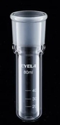
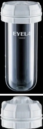
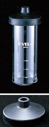
| (NEW) Freezing bottles | (Conventional) Freezing bottles | |
| 40 / 80mL type | 150 to 1200mL type | Cap: Made of chloroprene rubber (black) Glass bottle: Screwless |
| Neck : Taper joint, TS40/32 | Cap: Made of GFPP resin (white), separable into upper and lower parts with screws Glass bottle: With lip |
|
 |
 |
 |
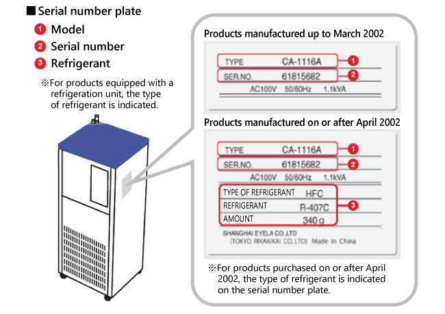
Please check the serial number plate affixed to the equipment main body.
The model, serial number, and refrigerant type are indicated on this plate.